By Ryan Boudreaux
| Introductory video (click play to watch video) |
Inspired by the article "Build a swinging gate for easy access" (http://www.trains.com/mrr/default.aspx?c=a&id=1100) by Gary Hoover published in the April 2007 issue of Model Railroader, I took the ideas in the piece and applied it to what was already my own accepted wisdom in tackling my layout design dilemma. After reading this piece of writing however, I felt it was missing more detail, and that I was left empty handed, or wanting to know more. So I set out to study what I could and what it would take to build my own swing gate. What follows in this tutorial is my step by step approach to solving one of the major hurdles that hindered further progress on my layout.
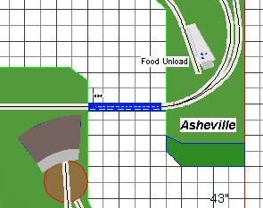 |
| Figure 1 (click for a larger view) |
A Plan of Action In my original track plan (see Figure 1) I have the aisle way track represented as a bridge, but I had not formalized the means of creating it in the form of a duck under, lift up section, or swing gate. I just knew that I needed the track to cross the aisle at that particular location in the track plan, how to get it done was still an option. After reading Hoover’s article I began formulating plans for a swing gate, and he gave me the jump start to move forward with tackling the problem of crossing the aisle way.
Using 3rd PlanIt track planning software I created an accurate scale drawing (see Figure 2) of the proposed swing gate, and using measurements that I took included the height on both sides of the aisle and the aisle way width at the top level of the benchwork. However, any CAD drawing software or even some good quality graph paper and some sharp pencils and scale rulers will do the job too.
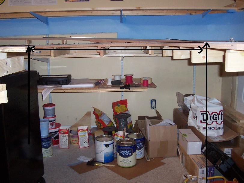
Before I began the swing gate design I found out that the left side of the benchwork was about 1/16” too high, so to make them both level I lowered that side of the benchwork. It was important to me in keeping the benchwork level throughout the span between the spaces where the swing gate would be placed. With notepad and pencil in hand I took all the measurements with my tape measure that I could. (See image 1 and 2) I transferred from my notes the accurate measurements of height on both sides and drew the existing benchwork into the drawing, and then I spaced them the appropriate width apart in the diagram.
 |
| Figure 2 (click for larger view) |
I then filled in the drawing of how I wanted the swing gate to look based on the pre-defined dimensions of the actual existing benchwork. After all the drawings looked right and I had my forms in place I copied the dimension properties in the drawing that I would need for each piece of the swing gate project and these are noted at the bottom of the swing gate plan drawing (Figure 2) and also in the materials list (Table 1).
Your situation will vary depending on the location of the area on your layout to incorporate a swing gate, but the measuring requirements are the same. Height of the benchwork on both sides and the width between them in aisle way space are the main constraints. The other major measurement to determine is the width of the swing gate. For my benchwork building of single track alignments I like to have at least a 3” wide sub-roadbed or plywood base for my HO scale layout. (See figure 3) So I selected the width of the sub- roadbed plywood portion of the swing gate to be 3 inches. If you are doing a double track tangent line in HO scale with track centers 3” apart you should consider a minimum of 6 inches width for the swing gate.
 |
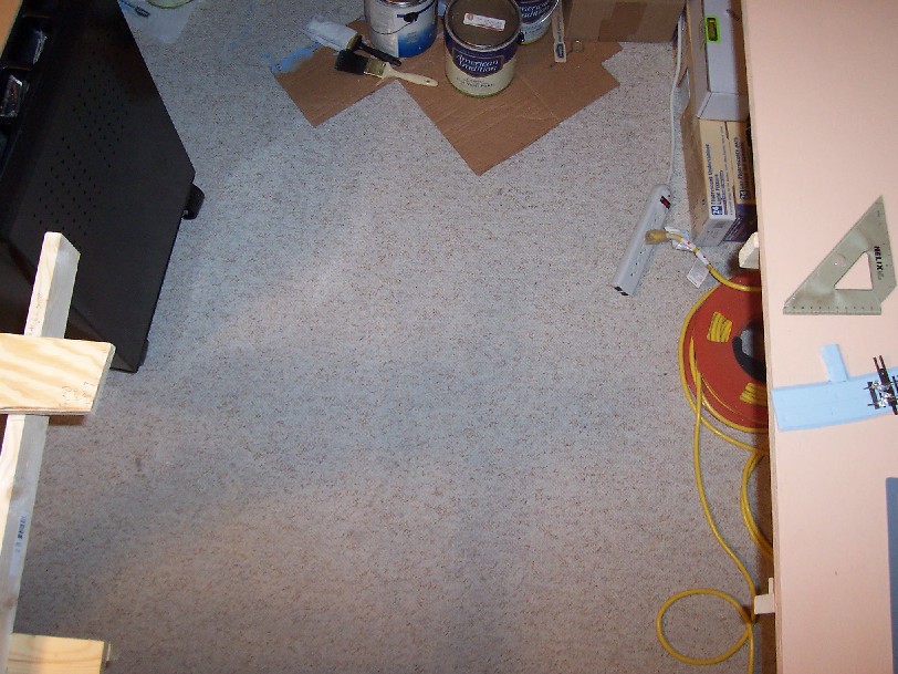 |
| Image 1 (click for larger view) | Image 2 (click for larger view) |
 |
| Figure 3 - (click for larger view) |
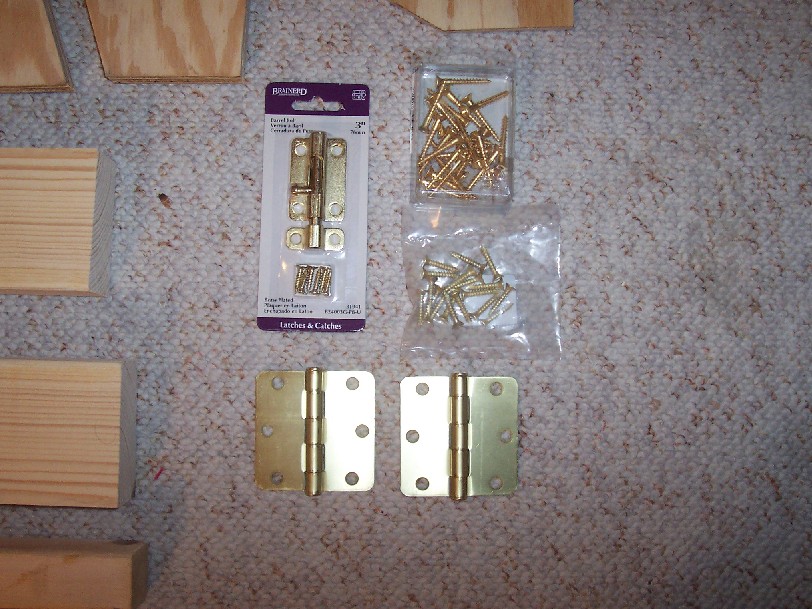
I designed the shape and function of the swing gate with properties similar to how a door is built. I added hinges and a bolt latch to the design so that the swing gate could move from the closed position to the open position, and the bolt latch at the opposite end so that it could be steadied when it is set for rail activity. I also wanted something of solid construction, but not too heavy, that is why I decided that the swing hinge side frame support would need to a 2” X 4” and the L-frame of the swing gate would be 2” X 4” construction as well. The throw side of the frame is 2” X 2” construction; no weight is bearing on this member, and is only used for the bolt throw stop for this side of the aisle way.
|
Materials List – Table 1
|
||
|
Quantity
|
Item
|
Measurements
|
|
1
|
2” X 4” Stud: L-Frame vertical member
|
14”
|
|
1
|
2” X 4” Stud: L-Frame horizontal member
|
27 15/16”
|
|
1
|
2” X 4” Stud: Frame member hinge side
|
38 11/16”
|
|
1
|
2” X 2” Frame member throw bolt side
|
38 11/16”
|
|
2
|
2” X 2” Frame members floor pieces
|
2’ and 3’
|
|
2
|
¼ ” Plywood (5 ply): Gusset members
|
4” X 17 7/16” X 21” X 4” X 23”
|
|
1
|
¾” Plywood (5 ply): Sub-roadbed member
|
3 ¼” X 27 1/2” X 3 1/6” X 26”
|
|
1
|
1” X 3” Spruce: Bolt throw plate
|
2 ½” X 1 3/16”
|
|
1
|
1” X 3” Spruce: Throw side apron
|
3 ¼” X 4” X 3” X 4 ½”
|
|
2
|
Brass hinges
|
3”
|
|
1
|
Brass dead bolt
|
3/8”
|
|
26
|
Brass flat head wood screws
|
1 ½” #10
|
|
8
|
Exterior deck screws
|
3 ½”
|
|
8
|
Exterior deck screws
|
2 ½”
|
|
2
|
Dry wall screws
|
1 ½”
|
|
1
|
Code 83 HO scale flex track segment
|
3’
|
|
1
|
Cork roadbed segment HO scale
|
3’
|
|
2
|
AGW 22 Electrical wire
|
12” each
|
Miscellaneous materials: Wood glue, gray latex caulk, CA adhesive, Walthers Goo adhesive, solder, flux.
|
Tools – Table 2
Note pad and pencil
Tape measure
Carpenters square
30” Level
Drill
Various size drill bits
Phillips head screw driver
Table or circular saw
C- Clamps
Putty knife
Utility knife
Micro blade hand saw - 0.04
Sander
Medium grit sand paper
Soldering iron |
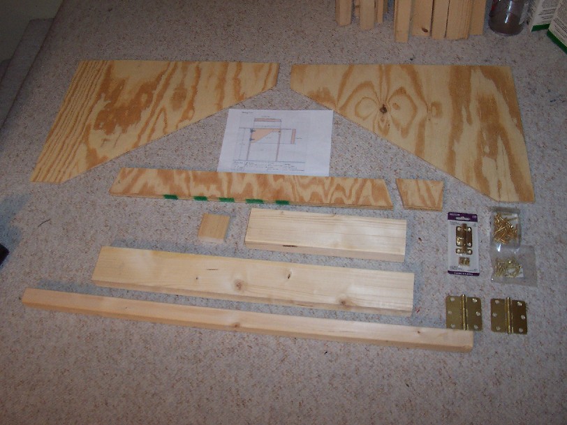 |
| Image 3 - (click for larger view) |
 |
| Image 4 - (click for larger view) |
Construction With the swing gate drawing in hand I marched on down to the local home improvement center and collected 1 - 8’ 2X4, 2 - 24” X 24” sheets of ¼” plywood, and most of the hardware required. I already had the ¾” plywood, the 2 X 2, and the 1 X 3 in stock. The actual measuring, cutting, and construction of the swing gate, frame, attaching it to the frame, adding the sub-roadbed and the receiving apron took only around 6 hours to complete. Here are the steps I took to build the frame, swing gate, and attach it to the frame.
 |
| Image 5 - (click for larger view) |
 |
| Image 6 - (click for larger view) |
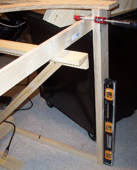
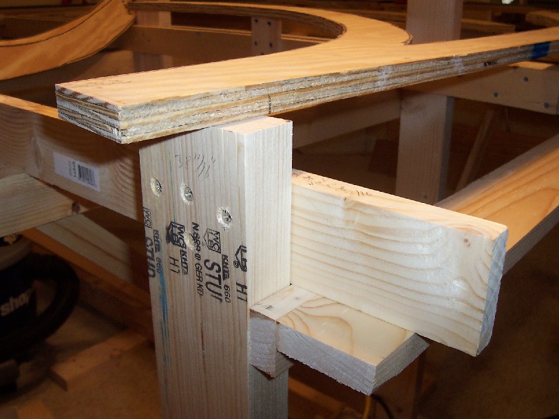
Frame I started with the 2” X 4” frame member for the hinge side of the swing gate and began by making final measurements of the benchwork to ensure proper placement. I lined up the 2X4 and verified the measurement again before making the final 38 11/16” cut. I positioned the 2X4 member and lined it up with the benchwork section and then clamped it to the joist of the adjoining benchwork (See image 5 & 6). I also lined up at the bottom of the 2X4 the 3’ 2X2 section that will be used to attach to the benchwork base and to the floor. Once everything was lined up and level I tightened the clamp on the 2X4 and benchwork joist. I then drilled 4 pilot holes in the 2X4 member and then screwed in 4 of the 2 ½” exterior deck screws. Then I drilled three pilot holes into the 2X2 and screwed 3 of the 3 ½” exterior deck screws through the 2X2, through the carpet and into the sub-flooring material. Then I checked for level again and drilled one pilot hole at the base of the 2X4 and centered it with the 2X2, and then set one more of the 2 ½” exterior deck screws into the 2X4. This completed the left side of the swing gate frame. (See image 7) I did the exact same on the other side for the throw bolt side of the swing gate frame, with the exception that I used 2X2’s for all materials and also set a screw to the benchwork from the top of the ¾” plywood and not to the joists.
 |
| Image 7 - (click for larger view) |
Making the cuts Once the frame was built I started on the swing gate portion of the project. With the measurements in hand I took the ¼” plywood, the remaining length of the 2X4 stud, some scrape ¾” plywood and the 1X3 portions and proceeded to the garage where my circular table saw is located. I measured and marked with a pencil all the appropriate cuts for the pieces, the final pieces were then brought back up to the train room. (See Image 3 above). One of the key features that I liked about the MR article was that Gary used a bias cut on both ends of the swing gate to facilitate a smoother opening and closing of the swing gate, and most importantly alignment of the track. In order to line up the sub-roadbed ¾” plywood portion of the swing gate I had to compensate for the existing benchwork on the left hand hinge side (See image 7) the benchwork overhangs by about 3” from the edge of the 2X4 frame. I cut that overhang off by about 2 inches; I knew I wanted to keep some of that overhang to compensate for the bias cut. The bias cut on the throw plate side of the swing gate sub-roadbed plywood section is 72º and the cut on the hinge side is 78º. I had to make sure that the length of the sub-roadbed plywood section of the swing gate would not be too long. By taking the aisle way width measurement and subtracting the amount of benchwork overhang I was able to approximate the length of the swing gate section by 1/16”. As a matter of fact the remaining piece of plywood from the 72º bias cut on the throw bolt side will be used as a variable alignment section when attaching the swing gate later on.
 |
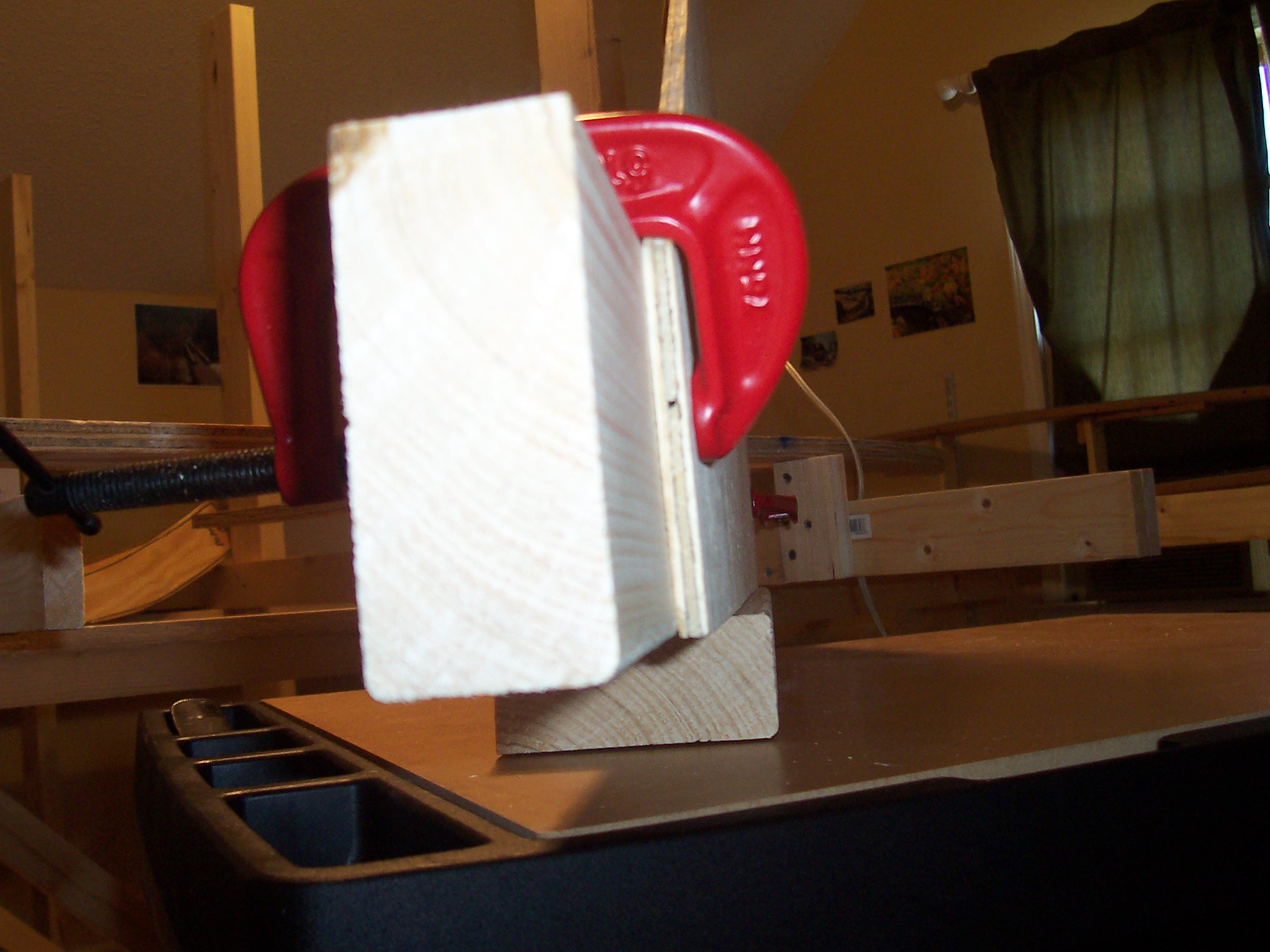
| Image 10 - (click for larger view) |
 |
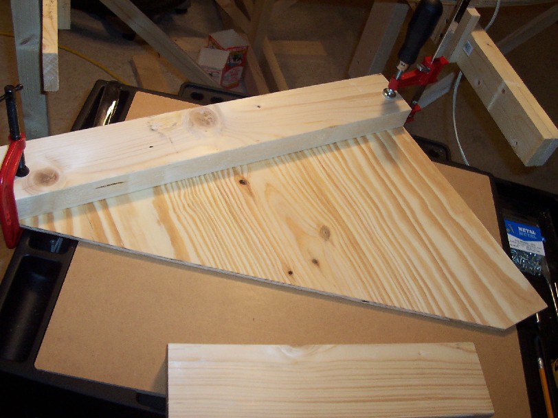
| Image 9 - (click for larger view) |
 |
| Image 8 - (click for larger view) |
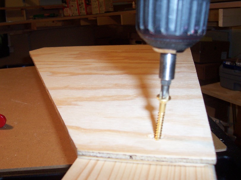
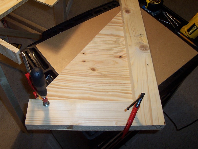
Building the swing gate Now that all the materials have been fabricated to their specific measurements it’s time to put them all together. I took one side of the ¼” plywood gusset and clamped it to the 2X2 horizontal member. (See image 8) Then to ensure that it was level on all sides I stood the parts on its side, and once I felt it was in alignment I applied a line of wood glue to each piece and then tightened up the clamps again and rechecked for alignment. (See image 9) Once the two pieces were lined up I turned the clamped pieces over and drilled 4 pilot holes and then set 4 ½” #10 brass screws through the top. (See image 10) I then clamped and aligned the other 2X4 member to the plywood gusset and attached it in the same manner as before. (See image 11) After the two 2X4 members were attached and secured I started with the other plywood gusset and attached it in the same manner, lined up and squared up with all the attached 2X4 members, drilled pilot holes, then set the screws in place. (See image 12) After the second plywood gusset was attached I double checked for alignment and then began the process of measuring and attaching the brass hinges.
 |
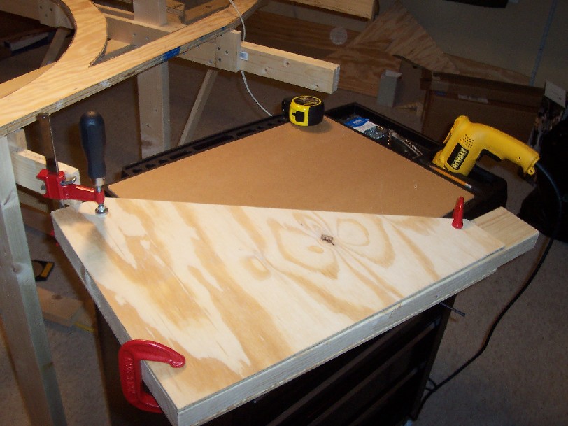 |
| Image 11 - (click for larger view) | Image 12 - (click for larger view) |
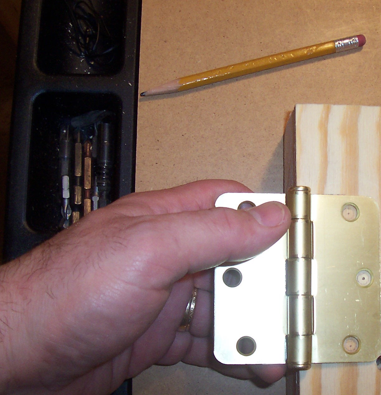
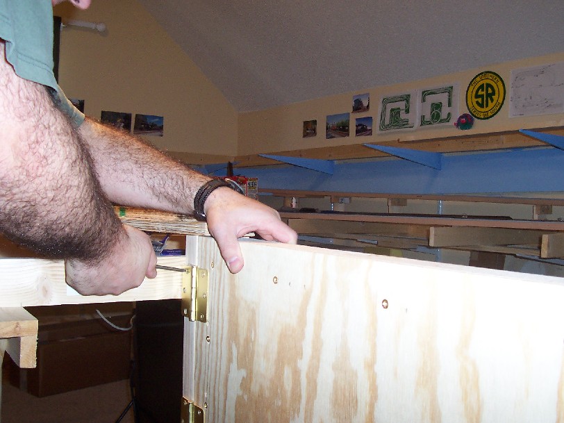
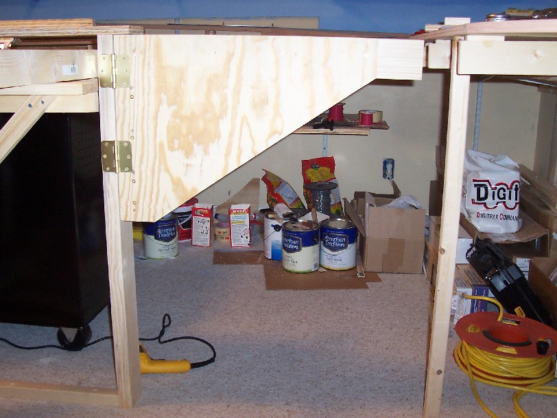
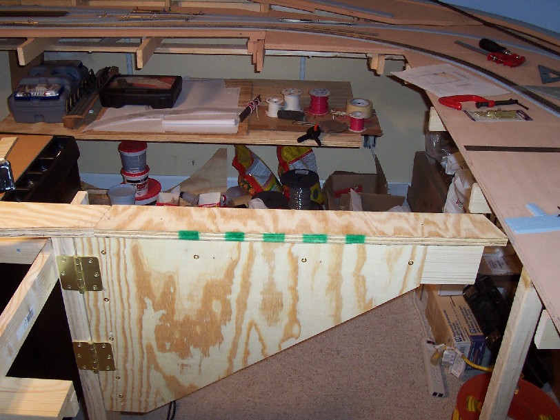
Hanging the Swing Gate I temporarily held the swing gate up to the 2X4 stud frame member to get the alignment and position needed to set the brass hinges in place. Using the holes of the brass hinges I marked the drill holes with a pencil and then measured again the positions to be sure that they would fit in alignment with the 2X4 stud frame and the vertical 2X4 of the swing gate. Once all alignment was correct I drilled the pilot holes for the brass hinge screws. Then I went back to the workbench and attached the brass 2 brass hinges to the swing gate. (See image 13) I attached both hinges with the middle hinge pin in centered alignment with the edge of the swing gate. After both hinges were secured to the swing gate I went back to the 2X4 frame member and aligned the hinges open end with the vertical stud, then I marked the pilot holes center with a pencil. While the swing gate rested on the workbench again I drilled pilot holes for the starter top screws for both hinges. Then while holding the swing gate in position with one hand I set the first of the 1 ½” #10 brass screws through the hinge and into the 2X4 frame stud. (See image 14) Checked for alignment again and then set the 2nd of the brass screws into the top hole of the bottom hinge. Checked for alignment again and then drilled the remaining 4 pilot holes and set the remaining brass screws. (See image 15)
 |
 |
 |
| Image 13 - (click for larger view) | Image 14 - (click for larger view) | Image 15 - (click for larger view) |
 |
| Image 17 - (click for larger view) |
 |
| Image 16 - (click for larger view) |
Setting the sub-roadbed At this point the project starts taking on the form of a functioning swing gate. Very similar to a door, the swing gate opens out to the left and into the facing aisle way space. Now it is time to add the sub-roadbed ¾” plywood piece. After placing the plywood piece on top of the swing gate I noticed that the sub-roadbed was just a bit lower than necessary to line up a level surface. (See image 16) So I decided to add shims to each side that would perfect the sub-roadbed alignment with both sides of the benchwork sections. I took measurements to determine the amount of vertical rise needed to shim up both sides of the sub-roadbed ¾” plywood. Then using a scrape piece of ¼” plywood I fashioned a section that would fit on the bolt latch side of the swing gate. I attached this shim with a good amount of Liquid Nails for Projects and allowed it to set for a few minutes. I also added another shim to raise the hinge side of the swing gate by about 1/8”. I positioned the pre-cut ¾” plywood sub-roadbed section butted against the hinge side of the existing benchwork edge and then marked on the existing benchwork the exact matching bias cut and then made a small alignment cut on the benchwork to match up the correct angle. Then I applied a layer of gray latex caulk on the top section of the shims just prior to attaching the sub-roadbed piece on top. I drilled 2 evenly spaced pilot holes centered with the horizontal 2X4 of the swing gate and then I set two 2 ½” exterior deck screws from the top of the ¾” plywood sub-roadbed. (See image17)
Receiving side of swing gate To match the bias cut on the throw bolt side of the swing gate I fashioned a bias cut apron and attached it to another section of ¾” plywood. Remember that left over piece of ¾” plywood from the original 70º cut on the sub-roadbed piece of the swing gate? (See image 18) Well that is the piece that will be used to match up that side of the swing gate to the benchwork. With the swing gate in closed position I measured the exact position of the receiving apron piece and marked it with a pencil where it aligned with the existing stationary benchwork. (See image 19 & 20) Then I cut the piece and glued it to the remaining ¾” plywood to form a base using Walthers Goo, and then I positioned a clamp and allowed the pieces to dry a bit. After the glue dried for a few minutes I then aligned the piece with the middle of the adjoining road bed center on the stationary benchwork, measured, and then attached the receiving apron to the stationary benchwork using a small bit of wood glue then clamped it, and then drilled a few pilot holes from the bottom and set 2 – 1 ½” drywall screws to complete the attachment. (See image 21) Then I tested the fit to ensure the alignment was tight but that the swing gate could negotiate the receiving apron (See Image 22). I then attached the throw plate to the 2X2 frame member so that I could attach the dead bolt to the swing gate. After alignment was checked I glued and set 2 – 2 ½” screws to attached the throw plate to the 2X2, then aligned, marked, and set the dead bolt to the swing gate and the bolt receiving end to the plate. (See image 23)
Check the next installment when I show you: